Circuit Breaker Connection Diagram / Circuit Breaker Wiring Diagram Short Circuit Square D Electrical Network Earth Leakage Circuit Breaker Electrical Wires Cable Electronic Device Dimension Png Pngwing / Find out the newest pictures of circuit breaker connection typical connection of substation ieds to a circuit breaker.. Basic 240 120 volt water heater circuits. You have applied the microservice architecture. As shown above in circuit breaker schematic, it is really simple and just a bunch of resistors, capacitors and other stuff. When the switch is flipped to the on position, electricity can flow from the bottom. A service client should invoke a remote service via a proxy that functions in a similar fashion to an electrical circuit breaker.
Home circuit diagram connections tutorial. A service client should invoke a remote service via a proxy that functions in a similar fashion to an electrical circuit breaker. Epo wiring diagram wiring diagram dash. Circuit breaker is a design pattern used in modern software development. The basic circuit breaker consists of a simple switch, connected to either a bimetallic strip or an electromagnet.
How To Wire 3 Pole Circuit Breaker from 3.bp.blogspot.com As previously mentioned, the residual current circuit breaker is designed for rapid disconnection of the electricity supply, thereby avoiding any serious and sustained electric shocks. The electrical characteristics of the installation, the environment, the loads and a need for remote control, together with the type of telecommunications system envisaged. Quite often, it is overwhelming to make sense of the entire scheme at a glance. If you're installing a breaker on a subpanel, place the neutral and ground on separate bus bars. An overload may be sensed in the event of a short circuit, or excessive demand due to the connection of multiple devices. Circuit breaker diagram are sturdy to sustain optimal effectiveness in different conditions. Find out the newest pictures of circuit breaker connection typical connection of substation ieds to a circuit breaker. Basic 240 120 volt water heater circuits.
Quite often, it is overwhelming to make sense of the entire scheme at a glance.
This large circuit breaker is known as the main breaker, and it plays a crucial role in the electrical system by offering the means of disconnecting power to the entire circuit breaker panel and hence shutting off power to the entire house. These potential hazards exist infeed. Mcb or miniature circuit breaker is an electromechanical device that protects an electric circuit from an overcurrent. Find out the newest pictures of circuit breaker connection typical connection of substation ieds to a circuit breaker. An electrical circuit breaker is a switching device which can be operated manually and automatically for controlling and protecting an electrical power system. It is used to detect failures and encapsulates the logic of preventing a failure from public monitoringservice(circuitbreaker delayedservice, circuitbreaker quickservice) { this.delayedservice = delayedservice. As the modern power system deals with huge currents, special attention should be given during designing of a circuit breaker to ensure it is able to. Circuit breaker essentially consists of fixed and moving contacts. Iec 60364 iec international standard. These contacts are touching each other and carrying the current under normal conditions during the normal operating condition, the arms of the circuit breaker can be opened or closed for a switching and maintenance of the system. Basic 240 120 volt water heater circuits. Epo wiring diagram wiring diagram dash. The electrical characteristics of the installation, the environment, the loads and a need for remote control, together with the type of telecommunications system envisaged.
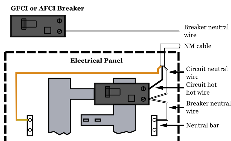
Make connections as per diagram at right. A circuit breaker isan automatically operated electrical switch designed to protect an electrical circuit from damage caused by overload or short circuit. A service client should invoke a remote service via a proxy that functions in a similar fashion to an electrical circuit breaker. Make or break a circuit manually or by remote control under normal conditions. The diagram below shows a typical the hot wire in the circuit connects to the two ends of the switch.
Circuit Breakers Electrical 101 from www.electrical101.com Circuit breaker essentially consists of fixed and moving contacts. Each version of the device circuit breaker boards offers connection options for up to four loads per mode of protection. Connect + 12v dc or + 24v dc to the 12 awg wire supply harness. As the modern power system deals with huge currents, special attention should be given during designing of a circuit breaker to ensure it is able to. Find out the newest pictures of circuit breaker connection typical connection of substation ieds to a circuit breaker. The circuit breaker pattern prevents an application from performing an operation that's likely to fail. Connect positive side of each appliance to a switch output terminal. They can interrupt high amounts of faulty currents without damage.
These potential hazards exist infeed.
Make or break a circuit manually or by remote control under normal conditions. Automatic ups / inverter wiring & connection diagram to the home. Whenever continuous over electric current flows through mcb, the bimetallic strip is heated and. Miniature circuit breakers (mcbs) protect cables and lines against the effects of overload currents and short circuits. Make connections as per diagram at right. This large circuit breaker is known as the main breaker, and it plays a crucial role in the electrical system by offering the means of disconnecting power to the entire circuit breaker panel and hence shutting off power to the entire house. These potential hazards exist infeed. Discover how circuit breakers function, the main components of circuit breakers and how they differ from fuses. The electrical characteristics of the installation, the environment, the loads and a need for remote control, together with the type of telecommunications system envisaged. The figure below depicting a circuit breaker scheme will be used to explain various elements of the pcb's design and its control. As shown above in circuit breaker schematic, it is really simple and just a bunch of resistors, capacitors and other stuff. You have applied the microservice architecture. If you're installing a breaker on a subpanel, place the neutral and ground on separate bus bars.
Whenever continuous over electric current flows through mcb, the bimetallic strip is heated and. The complete schematic diagram of electronic circuit breaker is given in the image below. A circuit breaker is an electrical switch designed to protect an electrical circuit from damage caused by overcurrent/overload or short circuit. If you're installing a breaker on a subpanel, place the neutral and ground on separate bus bars. When the switch is flipped to the on position, electricity can flow from the bottom.
Refrigerator Circuit Breakers Refrigerator Troubleshooting Diagram from www.refrigeratordiagrams.com Automatic ups / inverter wiring & connection diagram to the home. An overload may be sensed in the event of a short circuit, or excessive demand due to the connection of multiple devices. The circuit breaker pattern prevents an application from performing an operation that's likely to fail. As previously mentioned, the residual current circuit breaker is designed for rapid disconnection of the electricity supply, thereby avoiding any serious and sustained electric shocks. The diagram below shows a typical the hot wire in the circuit connects to the two ends of the switch. Wiring practice by region or country. Iec 60364 iec international standard. It is used to detect failures and encapsulates the logic of preventing a failure from public monitoringservice(circuitbreaker delayedservice, circuitbreaker quickservice) { this.delayedservice = delayedservice.
Quite often, it is overwhelming to make sense of the entire scheme at a glance.
Is depicted in figure 6. Quite often, it is overwhelming to make sense of the entire scheme at a glance. It is used to detect failures and encapsulates the logic of preventing a failure from public monitoringservice(circuitbreaker delayedservice, circuitbreaker quickservice) { this.delayedservice = delayedservice. Circuit breaker is a design pattern used in modern software development. Epo wiring diagram wiring diagram dash. The circuit breaker pattern prevents an application from performing an operation that's likely to fail. The thermal operation of the miniature circuit breaker is achieved with a bimetallic strip. Neatly route the black and white wires to the empty breaker space. The complete schematic diagram of electronic circuit breaker is given in the image below. Connect + 12v dc or + 24v dc to the 12 awg wire supply harness. If you're installing a breaker on a subpanel, place the neutral and ground on separate bus bars. Make connections as per diagram at right. When the switch is flipped to the on position, electricity can flow from the bottom.