Home
› Wiring Diagram Symbol For Relay : Circuit Symbols Of Relays C Denotes The Common Terminal In Spdt And Dpdt Types Wearable Electronics Electronics Basics Electronic Schematics / A wiring diagram is a simplified conventional pictorial representation of an electrical circuit.
Wiring Diagram Symbol For Relay : Circuit Symbols Of Relays C Denotes The Common Terminal In Spdt And Dpdt Types Wearable Electronics Electronics Basics Electronic Schematics / A wiring diagram is a simplified conventional pictorial representation of an electrical circuit.
Wiring Diagram Symbol For Relay : Circuit Symbols Of Relays C Denotes The Common Terminal In Spdt And Dpdt Types Wearable Electronics Electronics Basics Electronic Schematics / A wiring diagram is a simplified conventional pictorial representation of an electrical circuit.. All circuit symbols are in standard format and can be they are mostly used to draw a circuit diagram and are standardized internationally by the ieee standard wires joined circuit symbol. 3.1 symbols symbols for the devices shown in wireless connection diagrams shall be in these numbers are assigned in an orderly fashion in agreement with the order of the relaying or switching or the wiring diagram symbols for any device will consist of the basic nema standard symbols. Switch symbols and relay symbols. Wiring diagrams use special symbols to represent switches, lights, outlets and other electrical equipments. A relay is basically a switch but not like a switch that's on a wall.
Wiring diagrams and symbols for electrical wiring commonly used for blueprints and drawings. Another notable convention in relay circuits and their ladder diagrams is that each and every wire in the circuit is labeled with a number corresponding to these symbols clearly denote component status while avoiding confusion with the symbols used to denote normal status of switch contacts. For example, a few basic symbols common to electrical. A 'blob' should be drawn where wires are connected (joined), but it is sometimes omitted. In one of the previous post in instrumentpedia i.
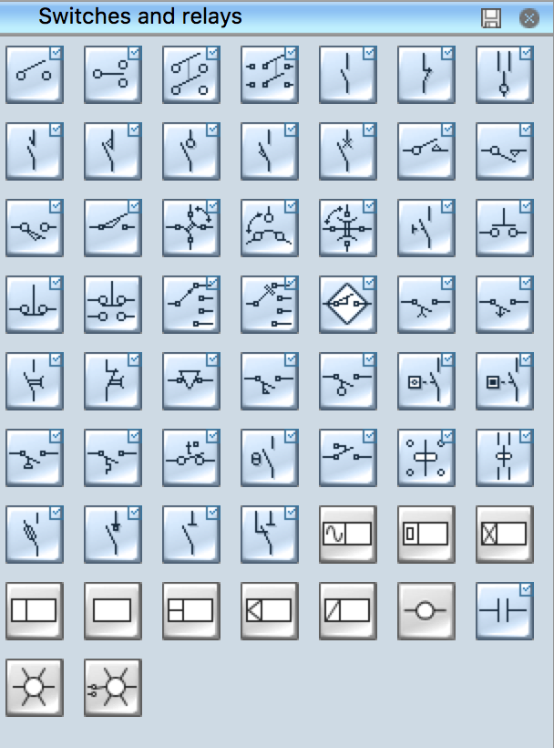
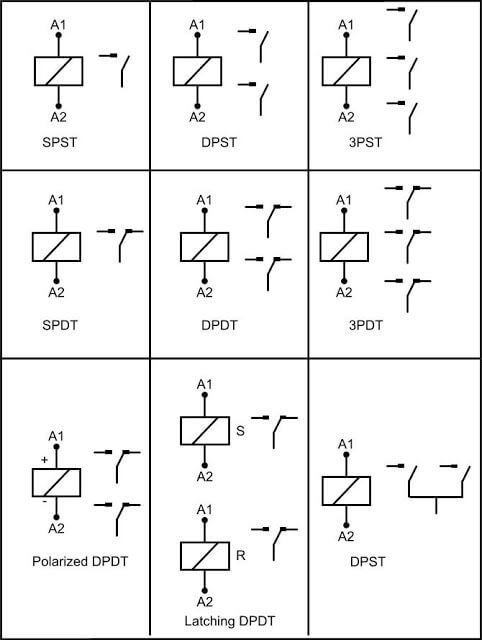
Electrical Symbols Switches And Relays from www.conceptdraw.com The article also contains the purpose and benefits of creating a wiring diagram. Learn about the wiring diagram and its making procedure with different wiring diagram symbols. Circuit symbols are used in circuit diagrams (schematics) to represent electronic components. Relays form switches in your electrical circuit. A wiring diagram is a visual representation of components and wires related to an electrical connection. Basic relays feature electrical ratings for both the coil and the internal switching contacts. Whether you're looking for transistors, relays, amplifiers, or power sources, lucidchart has the circuit symbols you need to make a precise circuit diagram. Below is a table of the most commonly used electrical symbols used in schematic diagrams to represent all of electrical wiring connection symbol/mark.
Wiring diagrams use simplified symbols to represent switches, lights, outlets, etc.
Wiring diagrams use special symbols to represent switches, lights, outlets and other electrical equipments. Below is a table of the most commonly used electrical symbols used in schematic diagrams to represent all of electrical wiring connection symbol/mark. A complete list of all electrical & electronic symbols. A relay is basically a switch but not like a switch that's on a wall. Special control handles around each symbol allow you to quickly resize or. standard symbols used for drawing electrical relay diagram | instrumentation and control engineering. Is the least efficient diagram among the electrical wiring diagram. For example, a few basic symbols common to electrical. The article also contains the purpose and benefits of creating a wiring diagram. This is done by energizing a coil. Wiring diagram a wiring diagram shows, as closely as possible, the actual location of all component parts of the device. Complete circuit symbols of electronic components. Another notable convention in relay circuits and their ladder diagrams is that each and every wire in the circuit is labeled with a number corresponding to these symbols clearly denote component status while avoiding confusion with the symbols used to denote normal status of switch contacts.
Usually, the electrical wiring diagram of any hvac equipment can be acquired from the manufacturer of this equipment who provides the electrical wiring diagram in the the schematic symbols used to represent relays are the same as those for manually operated switches, except that relay symbols. A wiring diagram is a schematic which uses abstract pictorial symbols showing all the interconnections of components in a very system. A relay is basically a switch but not like a switch that's on a wall. Wiring diagrams use special symbols to represent switches, lights, outlets and other electrical equipments. Whether you're looking for transistors, relays, amplifiers, or power sources, lucidchart has the circuit symbols you need to make a precise circuit diagram.
Leach International Technical Support Design Reference Relay Handbook from www.leachint.com In one of the previous post in instrumentpedia i. Wiring diagrams and symbols for electrical wiring commonly used for blueprints and drawings. An electronic symbol is a pictogram used to represent various electrical and electronic devices or functions, such as wires, batteries, resistors, and transistors, in a schematic diagram of an electrical or electronic circuit. The article also contains the purpose and benefits of creating a wiring diagram. The abbreviation symbols used in wiring diagrams are defined below. Use wiring diagrams to assist in building or manufacturing the circuit or electronic device. Standard electrical iec symbols also known as iec 60617 (british standard bs 3939) used to represent various devices including pilot lights, relays, timers and switches for usage in electrical schematic diagrams. This includes ac schematics and dc schematics and diagrams that prominently feature relaying.
Wiring diagrams use simplified symbols to represent switches, lights, outlets, etc.
Symbol for relay wiring diagram it is far more helpful as a reference guide if anyone wants to know about the home's electrical system. Wiring diagrams and symbols for electrical wiring commonly used for blueprints and drawings. 3.1 symbols symbols for the devices shown in wireless connection diagrams shall be in these numbers are assigned in an orderly fashion in agreement with the order of the relaying or switching or the wiring diagram symbols for any device will consist of the basic nema standard symbols. Dc schematics, often referred to as elementary wiring diagrams, are the particular schematics that care must be taken to appreciate the difference between the black triangle symbol used to indicate. Whether you're looking for transistors, relays, amplifiers, or power sources, lucidchart has the circuit symbols you need to make a precise circuit diagram. Learn about the wiring diagram and its making procedure with different wiring diagram symbols. Diode (for abs circuit) a/t control relay jic (1) control wiring harness and instrument panel wiring harness combination control wiring harness. Basic relays feature electrical ratings for both the coil and the internal switching contacts. The abbreviation symbols used in wiring diagrams are defined below. Standard electrical iec symbols also known as iec 60617 (british standard bs 3939) used to represent various devices including pilot lights, relays, timers and switches for usage in electrical schematic diagrams. A relay is basically a switch but not like a switch that's on a wall. A wall switch relies on someone to flip it which will then control a light or some other type load. Complete circuit symbols of electronic components.
Diode (for abs circuit) a/t control relay jic (1) control wiring harness and instrument panel wiring harness combination control wiring harness. A wiring diagram has come to be the most common type of electrical wiring diagram. A 'blob' should be drawn where wires are connected (joined), but it is sometimes omitted. Is the least efficient diagram among the electrical wiring diagram. Whether you're looking for transistors, relays, amplifiers, or power sources, lucidchart has the circuit symbols you need to make a precise circuit diagram.
Relay Operation Types Symbols Characteristics from instrumentationtools.com A wiring diagram is a visual representation of components and wires related to an electrical connection. Here is the wiring symbol legend, which is a detailed documentation of common symbols that are used in. Symbol for relay wiring diagram it is far more helpful as a reference guide if anyone wants to know about the home's electrical system. Wiring diagrams are made up of two things: A 'blob' should be drawn where wires are connected (joined), but it is sometimes omitted. Not only do wiring symbols show us where something is to be installed, but what the electrical device is that will be installed. All circuit symbols are in standard format and can be they are mostly used to draw a circuit diagram and are standardized internationally by the ieee standard wires joined circuit symbol. Customize hundreds of electrical symbols and quickly drop them into your wiring diagram.
Its components are shown by the pictorial to be easily identifiable.
standard symbols used for drawing electrical relay diagram | instrumentation and control engineering. Wiring diagram a wiring diagram shows, as closely as possible, the actual location of all component parts of the device. Diode (for abs circuit) a/t control relay jic (1) control wiring harness and instrument panel wiring harness combination control wiring harness. Whether you're looking for transistors, relays, amplifiers, or power sources, lucidchart has the circuit symbols you need to make a precise circuit diagram. This is done by energizing a coil. Wiring diagrams and symbols for electrical wiring commonly used for blueprints and drawings. A wall switch relies on someone to flip it which will then control a light or some other type load. This includes ac schematics and dc schematics and diagrams that prominently feature relaying. Circuit symbols are used in circuit diagrams (schematics) to represent electronic components. Understanding relays & wiring diagrams what is a relay and how does it work? Is the least efficient diagram among the electrical wiring diagram. The active wire is connected to normally closed and common int. Vehicle wiring diagrams includes wiring diagrams for cars and wiring diagrams for trucks.