Home
› 0-30V Variable Power Supply Circuit Diagram / 0 30v Variable Power Supply Circuit Diagram At 3a Eleccircuit Com : Current limit can be adjusted using r2 potentiometer and the output voltage can be adjusted from 1.2 volts to 30 volts using r8 potentiometer.
0-30V Variable Power Supply Circuit Diagram / 0 30v Variable Power Supply Circuit Diagram At 3a Eleccircuit Com : Current limit can be adjusted using r2 potentiometer and the output voltage can be adjusted from 1.2 volts to 30 volts using r8 potentiometer.
0-30V Variable Power Supply Circuit Diagram / 0 30v Variable Power Supply Circuit Diagram At 3a Eleccircuit Com : Current limit can be adjusted using r2 potentiometer and the output voltage can be adjusted from 1.2 volts to 30 volts using r8 potentiometer.. Toroidal transformer used as voltage source 230 v primary input secondary outputs 32 v ac 3.2 a 7 v ac 0.1 a 7v ac 0.3 a. This circuit diagram is given below. For smaller voltages, we normally use batteries as a in order to increase the upto 30v input of 30v should be applied. This is attained by adding two resistors r1 and r2 as shown in figure. When the resistors r1 and r2 are added the equation for the output voltage of 7805 becomes vout= vfixed.
Single power supply switch plus or minus power circuit diagram. This 30v variable power supply circuit is based on lm317 voltage regulator circuit. A straightforward yet an effective note: Circuit diagram and working explanation. The output current is 38ma, when the power supply 3v, the output current is 30ma, sbar and pbar end load capacity of.
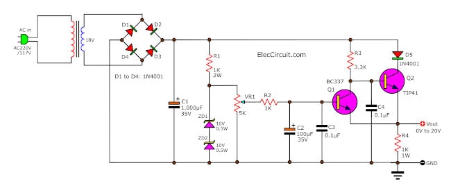
0 20v Variable Power Supply Circuit Diagram At 1a Eleccircuit Com from www.eleccircuit.com When the resistors r1 and r2 are added the equation for the output voltage of 7805 becomes vout= vfixed. I decided to see what i will get and whether it will be good. The above universal power supply circuit provides a variable voltage between 3 to 30v, the maximum current of 1.5a and addition of modules can provide a higher current. Single power supply switch plus or minus power circuit diagram. The output current is 38ma, when the power supply 3v, the output current is 30ma, sbar and pbar end load capacity of. Current limit can be adjusted using r2 potentiometer and the output voltage can be adjusted from 1.2 volts to 30 volts using r8 potentiometer. Sansui tv circuit diagram free download. Circuit diagram variable power supply circuit.
Sansui tv circuit diagram free download.
Here is the variable high voltage dc power supply circuit, which we can customize the output voltage from 0 to 311vdc, and it is protected the current over limit that we define at about 100 ma. 0.3 a 0.30 v adjusted lab power supply source eagle cad pcb schematic drawings and atmega644 code. Hello, friends in this video we will make a variable power supply. In this circuit, the maximum voltage at the output should be 30v so a 30v. The output current is 38ma, when the power supply 3v, the output current is 30ma, sbar and pbar end load capacity of. This is attained by adding two resistors r1 and r2 as shown in figure. Current limit can be adjusted using r2 potentiometer and the output voltage can be adjusted from 1.2 volts to 30 volts using r8 potentiometer. In the circuit you can see the t1 is a mains transformer with a ratio of 1:1, for security reasons. This 30v variable power supply circuit is based on lm317 voltage regulator circuit. The circuit for variable voltage unit using arduino is shown in below diagram. Here is the variable high voltage dc power supply circuit, which we can customize the output voltage from 0 to 311vdc, and it is protected the current over limit that we define at about 100 ma. The variable resistor r3 is used to set the current limiter, so your power supply will be save even when you short its output to ground. When the resistors r1 and r2 are added the equation for the output voltage of 7805 becomes vout= vfixed.
The 2n3055 power transistor for boost up current to 2amp. Here is the variable high voltage dc power supply circuit, which we can customize the output voltage from 0 to 311vdc, and it is protected the current over limit that we define at about 100 ma. The power mosfet q1 is controlled the current output, with using the resistor r3 500k adjust the voltage gate. In the circuit you can see the t1 is a mains transformer with a ratio of 1:1, for security reasons. The circuit for variable voltage unit using arduino is shown in below diagram.
Variable Voltage Current Power Supply Circuit Using Transistor 2n3055 Homemade Circuit Projects from homemade-circuits.com Unisen lt 40151 lcd tv pdf manual download. I decided to see what i will get and whether it will be good. The 2n3055 power transistor for boost up current to 2amp. The working and circuit is explained below. For smaller voltages, we normally use batteries as a in order to increase the upto 30v input of 30v should be applied. The above universal power supply circuit provides a variable voltage between 3 to 30v, the maximum current of 1.5a and addition of modules can provide a higher current. In the circuit you can see the t1 is a mains transformer with a ratio of 1:1, for security reasons. 0.3 a 0.30 v adjusted lab power supply source eagle cad pcb schematic drawings and atmega644 code.
The power supply ca handle as high as 10 amps which looks adequate for most electronic circuit requirement.
A variable dc power supply is very important for electronics projects, prototyping and hobbyists. The power supply ca handle as high as 10 amps which looks adequate for most electronic circuit requirement. This is a high quality power supply with a continuously variable stabilised output adjustable at any value between 0 and 30vdc. The mains features of this power supply is that it is highly flexible, and will allow you to get a variable voltage from 0 to 30 v, and a variable current from referring to the above proposed universal power supply circuit diagram, the functional details can be understood with the help of the flowing points Need part—you should use a transformer: Hello, friends in this video we will make a variable power supply. Circuit diagram and working explanation. In this circuit, the maximum voltage at the output should be 30v so a 30v. Current limit can be adjusted using r2 potentiometer and the output voltage can be adjusted from 1.2 volts to 30 volts using r8 potentiometer. The variable resistor r3 is used to set the current limiter, so your power supply will be save even when you short its output to ground. The 2n3055 power transistor for boost up current to 2amp. I decided to see what i will get and whether it will be good. In the circuit you can see the t1 is a mains transformer with a ratio of 1:1, for security reasons.
The above universal power supply circuit provides a variable voltage between 3 to 30v, the maximum current of 1.5a and addition of modules can provide a higher current. Because it has a few parts,small,and cheapest than others circuit that same power. Hello, friends in this video we will make a variable power supply. Circuit diagram variable power supply circuit. Here is the variable high voltage dc power supply circuit, which we can customize the output voltage from 0 to 311vdc, and it is protected the current over limit that we define at about 100 ma.
How To Make Variable Lab Bench Power Supply Youtube from i.ytimg.com This is a high quality power supply with a continuously variable stabilised output adjustable at any value between 0 and 30vdc. The circuit schematic diagram is shown below. I decided to see what i will get and whether it will be good. Because it has a few parts,small,and cheapest than others circuit that same power. You will able to adjust the output voltage. Circuit diagram of voltage regulator for adjustable 0 to 30v 2a dc power supply. The working and circuit is explained below. This variable power supply unit contains button interface for the voltage programming.
Power supply for electronic circuit experiments need some special features.
In the power supply circuit designed here, bipolar junction transistor 2n3055 works in the linear mode along with a variable resistance. .variable power supply with current control schematic diagram you will able to adjust the output voltage from 0 volt up to 30 volt circuit 13.8 volt 20 a transformerless power supply schematic diagram this 13.8 volt 20 a regulated transformerless power. In this circuit, the maximum voltage at the output should be 30v so a 30v. Unisen lt 40151 lcd tv pdf manual download. The 2n3055 power transistor for boost up current to 2amp. 0.3 a 0.30 v adjusted lab power supply source eagle cad pcb schematic drawings and atmega644 code. Parts list for diy bench power supply. Here is the variable high voltage dc power supply circuit, which we can customize the output voltage from 0 to 311vdc, and it is protected the current over limit that we define at about 100 ma. The circuit schematic diagram is shown below. The output current is 38ma, when the power supply 3v, the output current is 30ma, sbar and pbar end load capacity of. High efficiency variable regulator that new circuit design using ic regulator ua723 and tip3055 easy to build and small as power protect over load maximum 3a. You will able to adjust the output voltage. This circuit diagram shows you how to make a 5v to 12v variable dc power supply from a fixed 5v regulator ic 7805.