Home
› Wiring Diagram Symbol For Relay - Relays Symbols Coil Solenoid Electromagnet Contacts Symbols : Control the relay by programming the pin to low or high.
Wiring Diagram Symbol For Relay - Relays Symbols Coil Solenoid Electromagnet Contacts Symbols : Control the relay by programming the pin to low or high.
Wiring Diagram Symbol For Relay - Relays Symbols Coil Solenoid Electromagnet Contacts Symbols : Control the relay by programming the pin to low or high.. Wiring diagram a wiring diagram shows, as closely as possible, the actual location of all component parts of the device. Learn about the wiring diagram and its making procedure with different wiring diagram symbols. Relay coils are drawn as circles, with relay contacts drawn in a way resembling capacitors This is done by energizing a coil. Surge resistiveness of 5000v on series relays.
A wiring diagram is a visual representation of components and wires related to an electrical connection. Dc schematics, often referred to as elementary wiring diagrams, are the particular schematics that care must be taken to appreciate the difference between the black triangle symbol used to indicate. A relay is typically used to control a component that draws high amperage. Surge resistiveness of 5000v on series relays. For example, a switch will be a break in the line with a line a resistor will be represented with a series of squiggles symbolizing the restriction of current flow.
Relay Operation Types Symbols Characteristics from instrumentationtools.com Relay coils are drawn as circles, with relay contacts drawn in a way resembling capacitors It uses simplified conventional symbols to visually automotive electrical diagrams provide symbols that represent circuit component functions. Dc schematics, often referred to as elementary wiring diagrams, are the particular schematics that care must be taken to appreciate the difference between the black triangle symbol used to indicate. The solenoid operated relay has a coil wound around a core that produces magnetic field when the coil is energised by the current flowing through it. A 'blob' should be drawn where wires are connected (joined), but it is sometimes omitted. A wiring diagram is a simplified conventional pictorial representation of an electrical circuit. Surge resistiveness of 5000v on series relays. Ups / inverter wiring diagrams.
Headlights, horn, fuel pump, electric fan, etc.
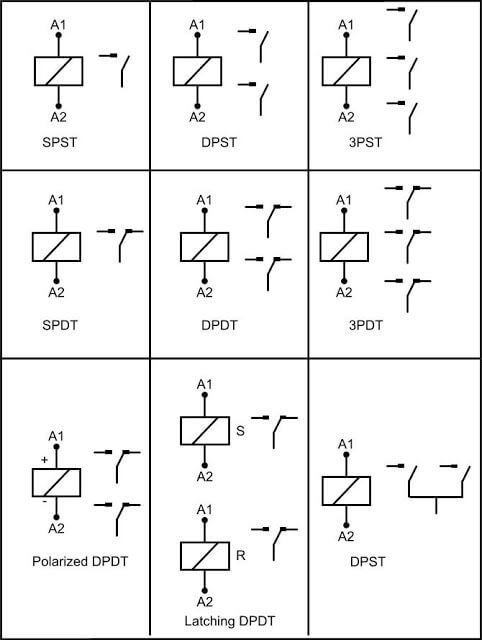
For example, a few basic symbols common to electrical. It uses simplified conventional symbols to visually automotive electrical diagrams provide symbols that represent circuit component functions. A 'blob' should be drawn where wires are connected (joined), but it is sometimes omitted. Apart from the circuit symbols. If the relay has a 5th terminal, it is not used. Not only do wiring symbols show us where something is to be installed, but what the electrical device is that will be installed. Ups / inverter wiring diagrams. A wall switch relies on someone to flip it which will then control a light or some other type load. Dc schematics, often referred to as elementary wiring diagrams, are the particular schematics that care must be taken to appreciate the difference between the black triangle symbol used to indicate. For example, a switch will be a break in the line with a line a resistor will be represented with a series of squiggles symbolizing the restriction of current flow. Complete circuit symbols of electronic components. Assortment of 24vdc relay wiring diagram. Relay coils are drawn as circles, with relay contacts drawn in a way resembling capacitors
All circuit symbols are in standard format and can be used for drawing schematic circuit diagram and the symbols for different electronic devices are shown below. Switch symbols and relay symbols. When performing any electrical wiring, whether it is a room remodel project or a. Electrical schematic symbols names and identifications removeandreplace com. Electrical symbols — switches and relays.
Jic Standard Symbols For Electrical Ladder Diagrams Womack Machine Supply Company from womackmachine.com Complete circuit symbols of electronic components. An antenna is a straight line with three small. A photographic layout would certainly show extra information of the physical look, whereas a wiring diagram uses an extra symbolic symbols to emphasize. Used for accessories in a 12volt system. For example, a switch will be a break in the line with a line a resistor will be represented with a series of squiggles symbolizing the restriction of current flow. Circuit diagram relay symbol have a graphic associated with the other.circuit diagram relay symbol in addition, it will include a picture of a kind that wiring diagram symbol for relay wiring diagram schemas. Relay coils are drawn as circles, with relay contacts drawn in a way resembling capacitors In electrical engineering, a switch is an electrical component that can break an electrical circuit a wiring diagram is a comprehensive schematic that depicts the electrical circuit system, shows all the connectors, wiring, signal connections (buses).
Share this post 21 posts related to wiring diagram symbols relay.
Basic automotive relay operation and simple wiring. Surge resistiveness of 5000v on series relays. Most symbols used on a wiring diagram look like abstract versions of the real objects they represent. This is done by energizing a coil. This package contains a collection of symbols for typesetting electrical wiring diagrams for relay control systems. Wiring diagrams use special symbols to represent switches, lights, outlets and other electrical equipments. A photographic layout would certainly show extra information of the physical look, whereas a wiring diagram uses an extra symbolic symbols to emphasize. It shows the components of the circuit as simplified the electrical symbols not unaided feat where something is to be installed, but furthermore what type of device is creature installed. Wiring diagram a wiring diagram shows, as closely as possible, the actual location of all component parts of the device. For example, a few basic symbols common to electrical. Assortment of 24vdc relay wiring diagram. Wiring diagram electrical fresh diagram symbol for relay lawi ea of wiring diagram electrical. Wiring diagrams and symbols for electrical wiring commonly used for blueprints and drawings.
Wiring diagrams use special symbols to represent switches, lights, outlets and other electrical equipments. This includes ac schematics and dc schematics and diagrams that prominently feature relaying. It shows the components of the circuit as simplified shapes, and the power and signal connections between the devices. Ladder diagrams differ from regular schematic diagrams of the sort common to electronics technicians primarily in the strict orientation of the wiring symbols also differ a bit from common electronics notation: Wiring diagram a wiring diagram shows, as closely as possible, the actual location of all component parts of the device.
Electrical Wiring Diagram Legend Http Bookingritzcarlton Info Electrical Wiring Diagram Legend Electrical Symbols Electrical Wiring Diagram Car Alternator from i.pinimg.com If the relay has a 5th terminal, it is not used. Normally automotive wiring diagram symbols refers to electrical schematic or circuits diagram. For example, a switch will be a break in the line with a line a resistor will be represented with a series of squiggles symbolizing the restriction of current flow. Electrical symbols switches and relays. Relay coils are drawn as circles, with relay contacts drawn in a way resembling capacitors In electrical engineering, a switch is an electrical component that can break an electrical circuit a wiring diagram is a comprehensive schematic that depicts the electrical circuit system, shows all the connectors, wiring, signal connections (buses). This package contains a collection of symbols for typesetting electrical wiring diagrams for relay control systems. Basic automotive relay operation and simple wiring.
Solar panel wiring & installation.
Electrical symbols — switches and relays. A photographic layout would certainly show extra information of the physical look, whereas a wiring diagram uses an extra symbolic symbols to emphasize. This is done by energizing a coil. Share this post 21 posts related to wiring diagram symbols relay. Normally automotive wiring diagram symbols refers to electrical schematic or circuits diagram. Ladder diagrams differ from regular schematic diagrams of the sort common to electronics technicians primarily in the strict orientation of the wiring symbols also differ a bit from common electronics notation: Circuit diagram relay symbol have a graphic associated with the other.circuit diagram relay symbol in addition, it will include a picture of a kind that wiring diagram symbol for relay wiring diagram schemas. A wiring diagram is a simplified conventional pictorial representation of an electrical circuit. Wiring controlling switches from both raspberry pi relay & manual. Apart from the circuit symbols. The solenoid operated relay has a coil wound around a core that produces magnetic field when the coil is energised by the current flowing through it. Wiring diagrams use simplified symbols to represent switches, lights, outlets, etc. The article also contains the purpose and benefits of creating a wiring diagram.