Home
› 0-30V Variable Power Supply Circuit Diagram : 0 28v 6 8a Power Supply Circuit Using Lm317 And 2n3055 / A variable bench power supply is the most important tool for any diy maker cause while testing circuit it needs different values of voltage and current.
0-30V Variable Power Supply Circuit Diagram : 0 28v 6 8a Power Supply Circuit Using Lm317 And 2n3055 / A variable bench power supply is the most important tool for any diy maker cause while testing circuit it needs different values of voltage and current.
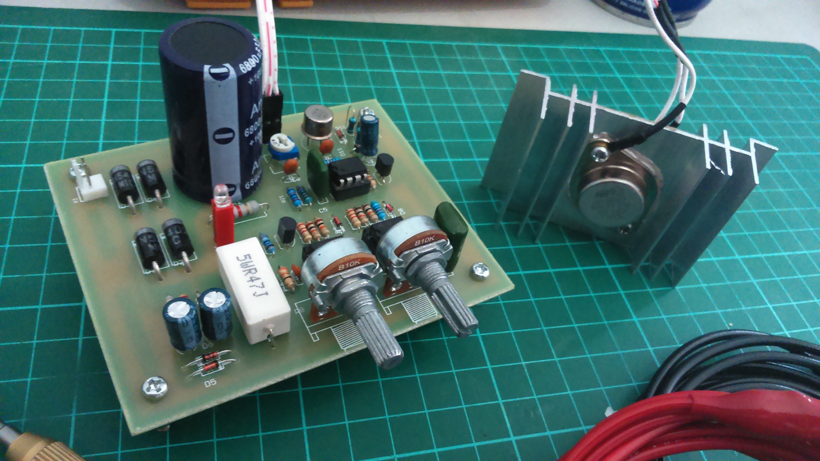
0-30V Variable Power Supply Circuit Diagram : 0 28v 6 8a Power Supply Circuit Using Lm317 And 2n3055 / A variable bench power supply is the most important tool for any diy maker cause while testing circuit it needs different values of voltage and current.. High efficiency variable regulator that new circuit design using ic regulator ua723 and tip3055 easy to build and small as power protect over load maximum. Today i seeks variable power supply circuit come to deposit again. The 2n3055 power transistor for boost up current to 2amp. While it is no powerhouse, it is quite satisfactory for testing all preamps, many other projects, and even most power amps, as long as there is no speaker connected. An 50v bench power supply can be made using electronic diagram below which is designed using lm10 op amp and 2n3055 transistors.
You will able to adjust the output voltage from 0 volt up to 30 volt dc. This is a high quality power supply with a continuously variable stabilised output adjustable at any value between 0 and 30vdc. You will have a very hard time even making a switching power supply of that size. Hey guyz, this time i'm making a variable bench power supply. Single power supply switch plus or minus power circuit diagram.
0 28v 6 8a Power Supply Lm317 2n3055 from electronics-diy.com A variable bench power supply is the most important tool for any diy maker cause while testing circuit it needs different values of voltage and current. The schematic diagram is based on the design case presented in the reference 1, designing switching voltage regulators with the. Power supply for electronic circuit experiments need some special features. Today i seeks variable power supply circuit come to deposit again. Here is the variable high voltage dc power supply circuit, which we can customize the output voltage from 0 to 311vdc, and it is protected the current over limit that we define at about 100 ma. In this circuit, the maximum voltage at the output should be 30v so a 30v. The main circuit topology is similar to that of the linear power supply. This circuit diagram shows you how to make a 5v to 12v variable dc power supply from a fixed 5v regulator ic 7805.
The schematic diagram is based on the design case presented in the reference 1, designing switching voltage regulators with the.
Hello, friends in this video we will make a variable power supply. High efficiency variable regulator that new circuit design using ic regulator ua723 and tip3055 easy to build and small as power protect over load maximum. Or will murphy get me this time? The main circuit topology is similar to that of the linear power supply. Circuit diagram variable power supply circuit. The mains features of this power supply is that it is highly flexible, and will allow you to get a variable voltage from 0 to 30 v, and a variable current from referring to the above proposed universal power supply circuit diagram, the functional details can be understood with the help of the flowing points In the circuit you can see the t1 is a mains transformer with a ratio of 1:1, for security reasons. A variable dc power supply is one of the most useful tools on the electronics hobbyist's workbench. This is a circuit diagram of a powersupply which provide 1.2 volts to 15 volts. The schematic diagram is based on the design case presented in the reference 1, designing switching voltage regulators with the. A variable bench power supply is the most important tool for any diy maker cause while testing circuit it needs different values of voltage and current. An 50v bench power supply can be made using electronic diagram below which is designed using lm10 op amp and 2n3055 transistors. Single power supply switch plus or minus power circuit diagram.
Diy variable power supply with adjustable voltage and current: The working and circuit is explained below. Single power supply switch plus or minus power circuit diagram. From the circuit diagram i have r7 is the only component connected in the return loop. You probably won't be able to build a linear power supply in a 5.5 x 5.5 box, unless you can have the box be a couple of feet tall.
0 30v Laboratory Power Supply Electronics Lab Com from www.electronics-lab.com The circuit for variable voltage unit using arduino is shown in below diagram. The working and circuit is explained below. This circuit diagram shows you how to make a 5v to 12v variable dc power supply from a fixed 5v regulator ic 7805. While it is no powerhouse, it is quite satisfactory for testing all preamps, many other projects, and even most power amps, as long as there is no speaker connected. Hello, friends in this video we will make a variable power supply. Today i seeks variable power supply circuit come to deposit again. Because it has a few parts,small,and cheapest than others circuit that same power. This circuit is not an absolute novelty, but it's simple.
Circuit diagram and working explanation.
The circuit for variable voltage unit using arduino is shown in below diagram. This is attained by adding two resistors r1 and r2 as shown in figure. Here's variable power supply voltage regulator circuit based around lm317 that provides fully regulated. Circuit diagram and working explanation. You will able to adjust the output voltage from 0 volt up to 30 volt dc. This circuit diagram shows you how to make a 5v to 12v variable dc power supply from a fixed 5v regulator ic 7805. Because it has a few parts,small,and cheapest than others circuit that same power. Hello, friends in this video we will make a variable power supply. An 50v bench power supply can be made using electronic diagram below which is designed using lm10 op amp and 2n3055 transistors. 30v 10a dc variable power supply circuit. When the resistors r1 and r2 are added the equation for the output voltage of 7805 becomes vout= vfixed. However, after the power transistor is in the switching state, the pulse width modulation (pwm) control technology has. You will have a very hard time even making a switching power supply of that size.
Here is the variable high voltage dc power supply circuit, which we can customize the output voltage from 0 to 311vdc, and it is protected the current over limit that we define at about 100 ma. An 50v bench power supply can be made using electronic diagram below which is designed using lm10 op amp and 2n3055 transistors. When the resistors r1 and r2 are added the equation for the output voltage of 7805 becomes vout= vfixed. The circuit for variable voltage unit using arduino is shown in below diagram. This is a circuit diagram of a powersupply which provide 1.2 volts to 15 volts.
30v 10a Bench Power Supply Variable 4 Digital Led Display Power Supp Dr Meter from cdn.shopify.com Will it work at first power on? The schematic diagram is based on the design case presented in the reference 1, designing switching voltage regulators with the. A variable bench power supply is the most important tool for any diy maker cause while testing circuit it needs different values of voltage and current. Join our community of 625,000+ engineers. While it is no powerhouse, it is quite satisfactory for testing all preamps, many other projects, and even most power amps, as long as there is no speaker connected. Hello, friends in this video we will make a variable power supply. This is a high quality power supply with a continuously variable stabilised output adjustable at any value between 0 and 30vdc. The ic used in this circuit is lm 1084 which is providing variable output with 3.
The working and circuit is explained below.
Motorola offers a wide range of power supervisory circuits that fulfill these needs. While it is no powerhouse, it is quite satisfactory for testing all preamps, many other projects, and even most power amps, as long as there is no speaker connected. A variable bench power supply is the most important tool for any diy maker cause while testing circuit it needs different values of voltage and current. A variable dc power supply is one of the most useful tools on the electronics hobbyist's workbench. In the power supply circuit designed here, bipolar junction transistor 2n3055 works in the linear mode along with a variable resistance. The working and circuit is explained below. 30v 10a dc variable power supply circuit. You will able to adjust the output voltage from 0 volt up to 30 volt dc. You will have a very hard time even making a switching power supply of that size. This variable power supply unit contains button interface for the voltage programming. This is attained by adding two resistors r1 and r2 as shown in figure. Will it work at first power on? The circuit for variable voltage unit using arduino is shown in below diagram.