Logic Flow Diagram Symbols / *BONUS* PowerPoint Flowcharts - These shapes are also called flowchart shapes.. A data flow diagram (dfd) maps out the flow of information for any process or system. It also gives insight into the inputs and outputs of each entity and the process itself. Er diagrams also are often used in conjunction with data flow diagrams (dfds), which map out the flow of information for processes or systems. In relay logic circuits, the contacts no and nc are used to indicate normally open or normally close relay circuit. These shapes are also called flowchart shapes.
Each step in a process is represented by a shape in a process map. The process flow chart provides a visual representation of the steps in a process. But with hold in logic both input a and input b are on the same rung as output y. These shapes are also called flowchart shapes. Er diagrams also are often used in conjunction with data flow diagrams (dfds), which map out the flow of information for processes or systems.
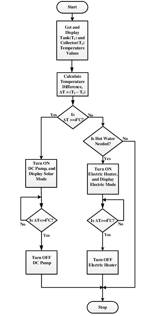
Flow chart showing control logic of the system controller Most members... | Download Scientific ... from www.researchgate.net Jul 19, 2021 · when mapping a process you simply draw a box for each step and connect them with arrows to show a flow. A relay logic circuit is a schematic diagram which shows various components, their connections, inputs as well as outputs in a particular fashion. Dfd does not have control flow and no loops or decision rules are present. Flow charts are also referred to as process mapping or flow diagrams. A basic process map would look like this; The flow of data of a system or a process is represented by dfd. It also gives insight into the inputs and outputs of each entity and the process itself. You can use an online tool to easily create a process map.
Electrical symbols and line diagrams chapter 3 material taken from chapter 3 of electric motor controls, g.
But with hold in logic both input a and input b are on the same rung as output y. Electrical symbols and line diagrams chapter 3 material taken from chapter 3 of electric motor controls, g. A circuit diagram (electrical diagram, elementary diagram, electronic schematic) is a graphical representation of an electrical circuit.a pictorial circuit diagram uses simple images of components, while a schematic diagram shows the components and interconnections of the circuit using standardized symbolic representations. These shapes are also called flowchart shapes. The process flow chart provides a visual representation of the steps in a process. Also, the way in which the latch is set and reset is done differently. Er diagrams also are often used in conjunction with data flow diagrams (dfds), which map out the flow of information for processes or systems. A basic process map would look like this; A relay logic circuit is a schematic diagram which shows various components, their connections, inputs as well as outputs in a particular fashion. Using hold in logic to achieve latching has a similar outcome to using set (latch) and reset (unlatch) symbols. May 26, 2020 · dfd is the abbreviation for data flow diagram. Flow charts are also referred to as process mapping or flow diagrams. In relay logic circuits, the contacts no and nc are used to indicate normally open or normally close relay circuit.
The process flow chart provides a visual representation of the steps in a process. Conceptdraw diagram is a perfect process flowchart software with rich flow chart templates and flow chart symbols you can create professional flow charts quickly and easily. Each step in a process is represented by a shape in a process map. A data flow diagram (dfd) maps out the flow of information for any process or system. The flow of data of a system or a process is represented by dfd.
Notation - Types, Rules, Advantages, Disadvantages, Example from www.brainkart.com Also, the way in which the latch is set and reset is done differently. A relay logic circuit is a schematic diagram which shows various components, their connections, inputs as well as outputs in a particular fashion. The process flow chart provides a visual representation of the steps in a process. May 26, 2020 · dfd is the abbreviation for data flow diagram. But with hold in logic both input a and input b are on the same rung as output y. Each step in a process is represented by a shape in a process map. Electrical symbols and line diagrams chapter 3 material taken from chapter 3 of electric motor controls, g. Flow charts are also referred to as process mapping or flow diagrams.
Er diagrams also are often used in conjunction with data flow diagrams (dfds), which map out the flow of information for processes or systems.
Nov 27, 2018 · ladder logic latch with hold in logic. Each step in a process is represented by a shape in a process map. It uses defined symbols like rectangles, circles and arrows, plus short text labels, to show data inputs, outputs, storage points and the routes between each destination. History of er models peter chen (a.k.a. You can use an online tool to easily create a process map. The process flow chart provides a visual representation of the steps in a process. Using hold in logic to achieve latching has a similar outcome to using set (latch) and reset (unlatch) symbols. Jul 19, 2021 · when mapping a process you simply draw a box for each step and connect them with arrows to show a flow. The flow of data of a system or a process is represented by dfd. Er diagrams also are often used in conjunction with data flow diagrams (dfds), which map out the flow of information for processes or systems. A circuit diagram (electrical diagram, elementary diagram, electronic schematic) is a graphical representation of an electrical circuit.a pictorial circuit diagram uses simple images of components, while a schematic diagram shows the components and interconnections of the circuit using standardized symbolic representations. Flow charts are also referred to as process mapping or flow diagrams. Dfd does not have control flow and no loops or decision rules are present.
Er diagrams also are often used in conjunction with data flow diagrams (dfds), which map out the flow of information for processes or systems. Conceptdraw diagram is a perfect process flowchart software with rich flow chart templates and flow chart symbols you can create professional flow charts quickly and easily. Each step in a process is represented by a shape in a process map. History of er models peter chen (a.k.a. May 26, 2020 · dfd is the abbreviation for data flow diagram.
Flowchart Symbols | Flow chart, Flow chart design, Process flow chart from i.pinimg.com But with hold in logic both input a and input b are on the same rung as output y. Nov 27, 2018 · ladder logic latch with hold in logic. The process flow chart provides a visual representation of the steps in a process. You can use an online tool to easily create a process map. Jul 19, 2021 · when mapping a process you simply draw a box for each step and connect them with arrows to show a flow. It also gives insight into the inputs and outputs of each entity and the process itself. Using hold in logic to achieve latching has a similar outcome to using set (latch) and reset (unlatch) symbols. History of er models peter chen (a.k.a.
History of er models peter chen (a.k.a.
But with hold in logic both input a and input b are on the same rung as output y. A data flow diagram (dfd) maps out the flow of information for any process or system. The flow of data of a system or a process is represented by dfd. History of er models peter chen (a.k.a. Also, the way in which the latch is set and reset is done differently. A basic process map would look like this; Jul 19, 2021 · when mapping a process you simply draw a box for each step and connect them with arrows to show a flow. Each step in a process is represented by a shape in a process map. A circuit diagram (electrical diagram, elementary diagram, electronic schematic) is a graphical representation of an electrical circuit.a pictorial circuit diagram uses simple images of components, while a schematic diagram shows the components and interconnections of the circuit using standardized symbolic representations. Using hold in logic to achieve latching has a similar outcome to using set (latch) and reset (unlatch) symbols. A relay logic circuit is a schematic diagram which shows various components, their connections, inputs as well as outputs in a particular fashion. In relay logic circuits, the contacts no and nc are used to indicate normally open or normally close relay circuit. It also gives insight into the inputs and outputs of each entity and the process itself.